| Home | Energy Physics | Nuclear Power | Electricity | Climate Change | Lighting Control | Contacts | Links |
|---|
NUCLEAR ELECTRICITY:
The most practical way to convert nuclear heat into electricity is by using the nuclear heat to produce high pressure steam. The steam is expanded through a steam turbine which directly drives an electricity generator to produce 60 Hz 3 Phase electric power.
The problem with this simple concept is that 20 MWe steam turbines, as contemplated for FNRs, typically operate at 10,000 RPM to 14,000 RPM, not at 1800 RPM of a typical 4 pole 60 Hz electricity generator. The classic solution to this problem is a gear drive between the turbine and the electricity generator. However, gear drives do not standup well to continuous full load service for over 200,000 hours as is required for public utility electricity generation. The solution contemplated herein is to have the steam turbine directly drive a high speed 2 pole 3 phase permanent magnet alternator that is designed for continuous operation at either 10,800 RPM or 14,400 RPM. The resulting high frequency output from the alternator is:
(10,800 RPM / 3600 RPM) X 60 Hz = 180 Hz
or
(14,400 RPM / 3600 RPM) X 60 Hz = 240 Hz
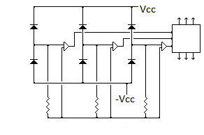
The electical energy output from the alternator will be down converted to 60 Hz 3 phase wye using solid state power inverter. This power inverter operates by rectifying the alternator 3 phase output to produce + Vcc and - Vcc DC rails with high ripple.
Assume that the high speed generator operates at 10,800 RPM and outputs 3 phase 180 Hz. In one 60 Hz cycle period each power rail will be charged with:
3 Phases X 1 pulse / phase-generator cycle X 3 generator cycles / 60 Hz cycle = 9 pulses.
Each 60 Hz cycle is formed using 18 states, with equal time increments. Thus each pulse causes one state incrementation.
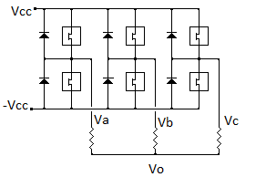
Consider a balanced 60 Hz load represented by a wye of equal resistors with external voltage connections Va, Vb, Vc and floating internal junction voltage Vo. Assume that for tabulation scaling purposes:
Vcc - (-Vcc)
= 1 - (-1) = 2
In the following table:
Va = voltage applied to terminal "a" of the equivalent wye load;
Vb = voltage applied to terminal "b" of the equivalent wye load;
Vc = voltage applied to terminal "c" of the equivalent wye load;
Vo = resulting voltage at the floating junction of the equivalent wye load resistances;
Vpa = Va - Vo = resulting net voltage across phase "a" load resistance;
Vpb = Vb - Vo = resulting net voltage across phase "b" load resistance;
Vpc = Vc - Vo = resulting net voltage across phase "c" load resistaqnce.
The various states of this network can be summarized as follows:
| Va | Vb | Vc | Vo | Vpa | Vpb | Vpc |
|---|---|---|---|---|---|---|
| NC | 1 | -1 | 0 | 0 | 1 | -1 |
| 1 | 1 | -1 | 1/3 | 2/3 | 2 / 3 | -4/3 |
| 1 | 1 | -1 | 1/3 | 2/3 | 2 / 3 | -4/3 |
| 1 | NC | -1 | 0 | 1 | 0 | -1 |
| 1 | -1 | -1 | -1/3 | 4/3 | -2/3 | -2/3 |
| 1 | -1 | -1 | -1/3 | 4/3 | -2/3 | -2/3 |
| 1 | -1 | NC | 0 | 1 | -1 | 0 |
| 1 | -1 | 1 | 1/3 | 2/3 | -4/3 | 2/3 |
| 1 | -1 | 1 | 1/3 | 2/3 | -4/3 | 2/3 |
| NC | -1 | 1 | 0 | 0 | -1 | 1 |
| -1 | -1 | 1 | -1/3 | -2/3 | -2/3 | 4/3 |
| -1 | -1 | 1 | -1/3 | -2/3 | -2/3 | 4/3 |
| -1 | NC | 1 | 0 | -1 | 0 | 1 |
| -1 | 1 | 1 | 1/3 | -4/3 | 2/3 | 2/3 |
| -1 | 1 | 1 | 1/3 | -4/3 | 2/3 | 2/3 |
| -1 | 1 | NC | 0 | -1 | 1 | 0 |
| -1 | 1 | -1 | -1/3 | -2/3 | 4/3 | -2/3 |
| -1 | 1 | -1 | -1/3 | -2/3 | 4/3 | -2/3 |
In the above table each of 18 states forming one 60 Hz period is represented by one table row. The period of each state is:
1 second / [60 (18)] = 9.25925 X 10^-4 seconds
The state count is advanced by pulses emitted by the rotation of the high speed generator. These pulses are initiated by detection of alternator phase voltage zero crossings.
Three rotations of the 2 pole alternator occur in one 60 Hz period which spans 18 states. Hence one rotation of the 2 pole alternator must cause the state counter to advance by:
18 states/ 3 rotations = 6 states / alternator rotation.
Each alternator rotation produces 1 cycle of 180 Hz. Each cycle has 3 phases. Thus if both rising edge and falling edge zero crossings are counted on all three phases we will get 6 pulses per alternator rotation. Thus each such pulse should increment the state count by one.
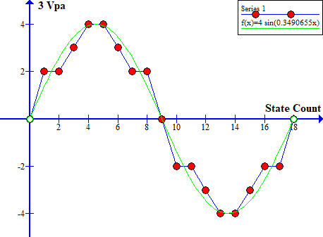
Plots of 3 Vpa, 3 Vpb and 3 Vpc as a function of state count yield three phase pseudo sine wave outputs. These outputs need to be low pass filtered with external transformers before being injected into the electricity grid. The green line shows an ideal sine wave for comparison.

The plots of 3 Vpb and 3 Vpc are identical to the plot of 3 Vpa but are phase shifted by 6 and 12 state counts.
An important feature of this 3 phase 60 Hz output is its change in frequency with a change in load. In order to properly simulate a synchronous mechanical generator the inverter output frequency must be a fixed fraction of the alternator shaft frequency. Thus the alternator output voltage zero crossings set the clock frequency of the inverter, likely via a phase lock loop. That feature enhances electricity system stability.
The voltage of this 3 phase output can be varied either with variable tap external transformers or by pulse width modulating the switching elements. It is not practical to vary the voltage by varing the alternator rotation rate due to the likely presence of mechanical resonances in either the steam turbine or the alternator at certain rotation rates. The alternator field is set by a permanent magnet that cannot be easily adjusted.
The quality of the sine wave outputs and the inverter efficiency can be improved by a combination of:
a) Low pass filtering;
b) Pulse width modulation of the switching elements;
c) Use of two parallel inverters, one of which is optimized to efficiently handle most of the power, the other which is optimized to suppress the switching harmonics. This technique is described in: Highly efficient three phase grid-connected parallel inverter system. Using this technique the claimed inverter efficiency is 97.86% and the claimed total harmonic distortionis 4.33%.
An important benefit of introducing pulse width modulation is that it allows trimming of the output voltage at a particular frequency, as is required for generator system load balancing.
The following illustrations show schematic diagrams of the high speed alternator connection and the switching portion of a 3 phase solid state power inverter.


An important issue is to identify generator manufacturers that can make 20 MWe 3 phase alternators that can continuously operate at 10,800 RPM to 14,400 RPM. A firm named Calnetix (Calnetix.com) claims to have a 2 MWe design with magnetic bearings. Their web site refers to "Design and Development of a Two-Megawatt High Speed Permanent Magnet Alternator for Shipping Applications".
This web page last updated June 20, 2020
| Home | Energy Physics | Nuclear Power | Electricity | Climate Change | Lighting Control | Contacts | Links |
|---|